Georgia
Institute of Technology’s Airborne Laser Induced Fluorescence Experiment (GITALIFE)
measurements of NO and NO2

Figure
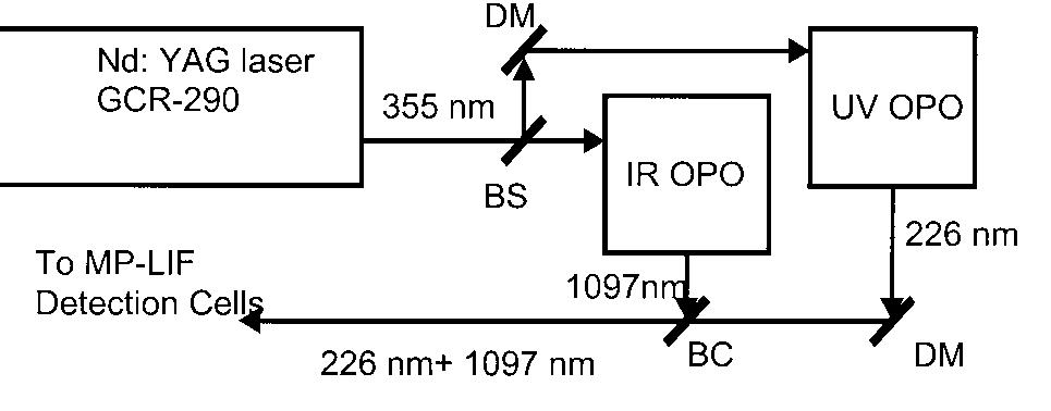
1. Schematic for MP‑LIF excitation sources, BC, BS are beam combining and
separating dichroic mirrors (DM).
In
this configuration, an injection seeded Quanta Ray GCR Nd:YAG laser is used as
the primary pump laser source for the OPOs. This system is capable of producing
the required wavelengths with sufficient energy while occupying less space and
weighing, ~700 lbs lighter, than our PEM Tropics system.
The frequency doubled output of one of the OPOs is used to generate
typically 4 mJ/pulse levels of 226 nm energy to excite an electronic NO
transition. While a second infrared
operated OPO is then used to generate typically 2 mJ per pulse of 1097 nm energy
to excite a rotational NO transition. This
system has a couple of unique design features that contribute to its
performance:
Spectroscopic
specificity from coincident excitation of two separate ro‑vibronically
resolved electronic transitions that enable dilution/calibration techniques to
be used
High
confidence in the measurements within transient (i.e., plume) events is
accomplished through the use of multiple detectors and double coincidence signal
processing techniques along with continuous monitoring of the instrument
background. The latter eliminates possible effects from spurious noise sources
such as cosmic rays, EMI, and/or aerosol scattered UV photons.
As in PEM‑Tropics, a 8 ns laser pulse from a Nd:YAG laser
photolyises the nitrogen dioxide molecules at 355 nm.
Quantitatively carrying out the photolytic conversion in a single laser
pulse has enabled us to greatly minimize potential interferences from
wall‑catalyzed thermal and photolytic processes. This permits us to design
a sample inlet system that capitalizes on the independence of the TP‑LIF
technique's signal strength and sensitivity on the flow rate through the sensor.
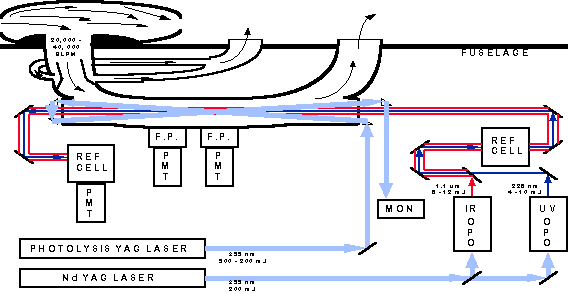
The modified sensor uses a large volume‑to‑surface ratio sampling
manifold that is fed at high flow‑rates (>3 x 10^4 lpm) using
ram‑air (see Figure 2).

Figure
2. Schematic representation of the sensor as it was deployed during NASA TRACE
P.
This configuration turns over the gas sample with in the manifold faster
than the laser pulse rate (i.e., sample residence time through instrument
<0.03 s whereas the pulse-to-pulse separation is 0.05 s). This short
residence time, large diameter flow system "effectively eliminates"
the possibility of interferences from wall‑catalyzed decomposition of
thermally labile nitrogen‑containing compounds such as HO2NO2.
Wall‑catalyzed photolytic interferences are also "effectively
eliminated" as only the central portion of the flow field (1 cm^2 of the 45
cm^2 full area) is probed within 50 ms by all lasers.
A computer controlled (and adjustable) 50 ms delay is used between the
photolysis laser pulse and the TP‑LIF NO fluorescence excitation laser
pulses. This time delay enables the nascent photo-fragmented NO population to
repartition into an ambient temperature Boltzmann distribution. In this scheme,
a single fluorescence monitoring cell is used to detect NO and NO2 on alternate
laser pulses. This configuration increases the absolute accuracy of the NO2
measurement by eliminating the subtle differences that can arise in previously
used separate NO and NO2 sampling cell arrangements